
The Rose Process
The Rose Geodesic process varies from the BF process by making the triangular grid subdivision directly on the spherical patch. There isn’t a significant difference in the end results between the Rose and BF process until the 3V. Even at the 3V stage the change is minimal. The Rose4V tessellation is the first clear display of improvement over the BF geodesics. Given this, and that we have already visited the lower frequencies using the BF method, lets begin with the Rose Geodesics 4V. As with the BF process we will ignore actual dimensions for this exploration. Keep in mind that all dimensions are controlled solely by a common variable which is the radius of the sphere being used.
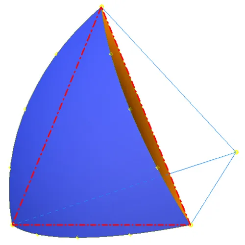
The Rose Geodesic process begins working directly with the spherical patch defined by the a single face of an inscribed platonic solid. This patch can be seen in Fig. 1 and is shown as the blue surface intersecting at the points of the planar face of the platonic solid (outlined in red.) The light blue line segments meet at the center of the sphere, and icosahedron in this case, and extend to the 3 corner points of the platonic solid face being used. Angles between each of these lines is identical and each of the nodes on the corners of the spherical patch are the same distance from the center point. Given this info it is clear that division of the arc length between any 2 corner nodes can be accomplished by dividing the internal angles between the lines by the frequency desired, 4 in this case, and calculating a new arc length. This single calculation will allow propagation of nodes around the entire perimeter of the spherical patch with equal spacing. Perimeter nodes are shown in yellow in Fig.1 along with the central point of the sphere.
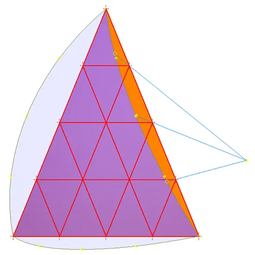
In Fig 2 the same spherical patch is shown transparent to show a planar triangle grid drawn on the icosahedron face. Line segments are extending from the center node indicating where nodes would be placed in the BF process. As seen the central node falls in the same location. This is to be expected with each even subdivision. However it is important to note that aside from corner nodes and the central even frequency nodes no other perimeter nodes will land in the same locations using the different processes. The BF process evenly divides a chord and then projects the divisions to the circular arc on the sphere. This works well for low frequency tessellations but greatly distorts the distances between the nodes as the frequency grows. As shown the Rose Geodesic process maintains truly equal spacing on all perimeter patch nodes.
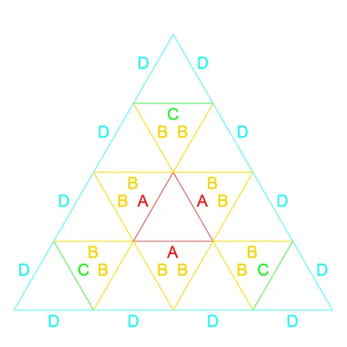
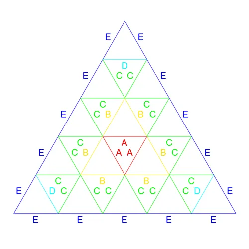
A geodesic patch map is a 2D layout of the order in which edges are labeled in relation to there lengths. Obviously this map can not be to scale as it is a 2D drawing of a layout which is following a spherical surface. In the Frequencies section the Rose Geodesic map labeling convention will be discussed in greater depth. At this point lets move along to a Rose4V Patch Map shown in Fig. 3. Being that all perimeter nodes are established we can observe that all edge lengths here labeled "D" and "C" have a determined length, assuming the spheres radius is established, set by the fixed location of the nodes around the perimeter of the spherical patch.
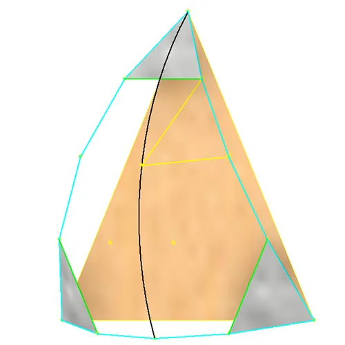
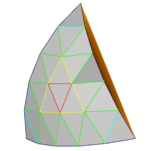
The established edges of the patch, "D" in cyan and "C" in green, are shown in Fig. 4. Established Faces are also shown in gray. The black circular arch is the intersection of a mirror plane for the patch and the spherical surface. Due to the 60 degree rotational symmetry of the patch the line may run through any of the patches point nodes. The 2 "B" Line segments shown in yellow are calculated with a number of constraints: 1 line must begin on a node connected to the line connecting 2 perimeter nodes, of the corner which the black line intersects, and end on a new node on the Black line towards the center of the patch; the 2nd line needs to have one end lie on the same node on the black line as the 1st and end on the next node towards the center of the same perimeter edge as the 1st begins on; the length of these two new line segments must also be equal.
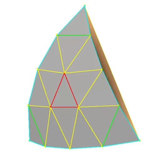
These new line segments can now be propagated around the patch. Each perimeter line segment, excluding the ones attached to a corner, will host a line from each end. These internal line segments attached to the nodes of a perimeter line segment will share a new node riding on the spherical patch surface as shown in Fig. 5. Given the uniform distances of the nodes along the perimeter and the equal lengths of the internal line segments, terminating on the uniform spherical surface, the spacing of these new internal nodes will also share an equidistant characteristic. These new internal nodes can now be connected with new equal length line segments following the basic triangular pattern as shown by the red lines in Fig.5. In this case an equilateral triangle is the result as there are only 3 new nodes are created. In higher frequency operations more nodes will be present for this step of subdivision. In any case the connection of nodes, greater than 3, will always mimic the triangular pattern displayed by the outer perimeter.
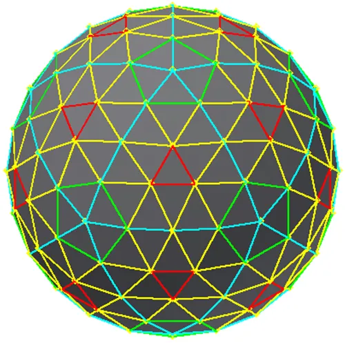
Fig. 6 shows the tiling of the Rose4V patch on the sphere. This frequency of tessellation is the beginning of a highly refined approximation of a sphere. Rose4V exhibits the continuation of the 1:1 liner progression of the Rose Geodesic process while the BFProcess begins its rapid deterioration into an exponential growth pattern.
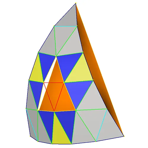
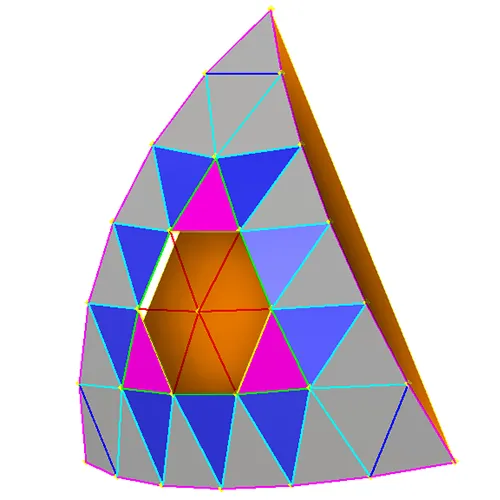
The Rose5V patch tessellation will allow a us to build a better understanding of the simplified repetitive nature of the Rose Geodesic process. Figure 7 displays nodes on the same spherical patch as in other frequencies. This is all shown over a, orange, face of the inscribed Icosahedron. This patch process began the same as the Rose4V but beginning with a 5 segment perimeter. Following the process as shown in the Rose4V example we are left with E, D, and C edge lengths on the Rose5V patch. All faces shown in grey are determined. Establishing the nodes at the inner point on the yellow face needs to be determined. This is achieved by propagating pairs of C line segments down the edge to underutilized perimeter segments to create ECC triangles. The inner CC nodes of these faces must also be located on the spherical surface. Fixing these nodes then allows us to determine the the B edges as well as the blue faces in Fig. 7. Moving forward the remaining edge length is trivial to determine given the existence of the remaining underutilized nodes. The “A” edges as shown in the Rose5V Patch Map, Fig 8, allow for the determination of the remaining faces. All determined faces are shown grey in Fig. 9. As one may begin to recognize thus far the Rose process requires the determination of one greater quantity of edge lengths for each increase of frequency. Of course the tessellation of these patches across the sphere remains the same regardless of the frequency.
Let us note the basic pattern of the process. Preparation) for an "n" Frequency Rose Geodesic Tesselation, Rose(n)V, place n+1 equally spaced nodes along each of the spherical patch cords. Step A) Determine edge lengths along inner most under-utilized cords (note that for the first step these are the original spherical patch cords. If the entire triangular grid is complete then stop. Step B) Determine segments on the innermost triangular corners. If the entire triangular grid is complete then stop. Step C) Determine line segments to make triangular faces pointing inwards from the most inner perimeter and propagate these around the perimeter establishing the inner nodes. If the entire triangular grid is complete then stop. If not then return to Step A.
The preparation step only happens once however the steps of the process may be repeated many times depending on the frequency . For ease of reference let us add sub-notation to each step to keep track of where we are in the process. The basic flow will evolve as such: Preparation; A1; B1; C1; A2; B2; C2; A3; …; (A||B||C)n. Simply put this is just repeating the series of steps A B C in order and incrementing the sub-notation until we reach the last step which will be Step (A or B or C) with whichever increment of the series we finish on. Revisiting the Rose5V now we can relate the steps to the edge lengths as such: Step A1 yielded edge E; B1 → D; C1 → C; A2 → B; B2 → A.
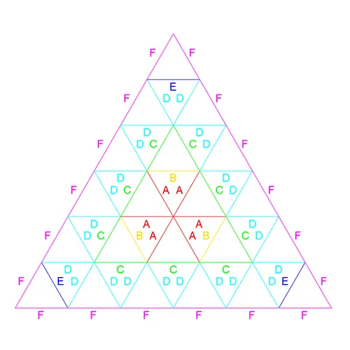
To firm up our understanding of this process let us carry forward with an overview of the Rose6V patch. To aid in the overview lets preview the Rose6V Patch Map which can be seen in Fig. 10. As previously mentioned the number of unique edge lengths are equal to the frequency of the tessellation. As expected we can see that the Rose6V will have 6 unique edge lengths. We can work with the above notation to move quickly through this process on a high level and also aid us in better understanding the frequency mapping in the next section.
Figure 11 shows us the all the edges obtained in the Rose6V process. Faces determined in the first 5 steps are shown as well. Rose6VPreparation: Nodes placed around spherical patch chords. A1: F length determined by connecting nodes. B1: E determined by connecting the 2 closest nodes from each corner. C1: 3rd node for the EDD face determined; D length determined; remaining DDF nodes determined. A2: C length determined B2: B length determined C2: Remaining BAA node determined; A length determined. A quick note on faces and timing. Technically the faces shown here in dark blue, and magenta, as well as the edge lengths C and B are defined in step C1 with the creation of nodes. However, for our purposes, we will consider them part of the step associated with verifying their last edge lengths. For example A2 → C and the blue (DDC) faces, B2 → B and magenta (CCB) faces.
We have explored the Rose4V through Rose6V patch tessellations. Moving forward we can repeat the process for any frequency tessellation using this process. Let us now move our attention to frequencies. for a better understanding of mapping and where we are navigating towards from the beginning.